

Rail way industrial equipments


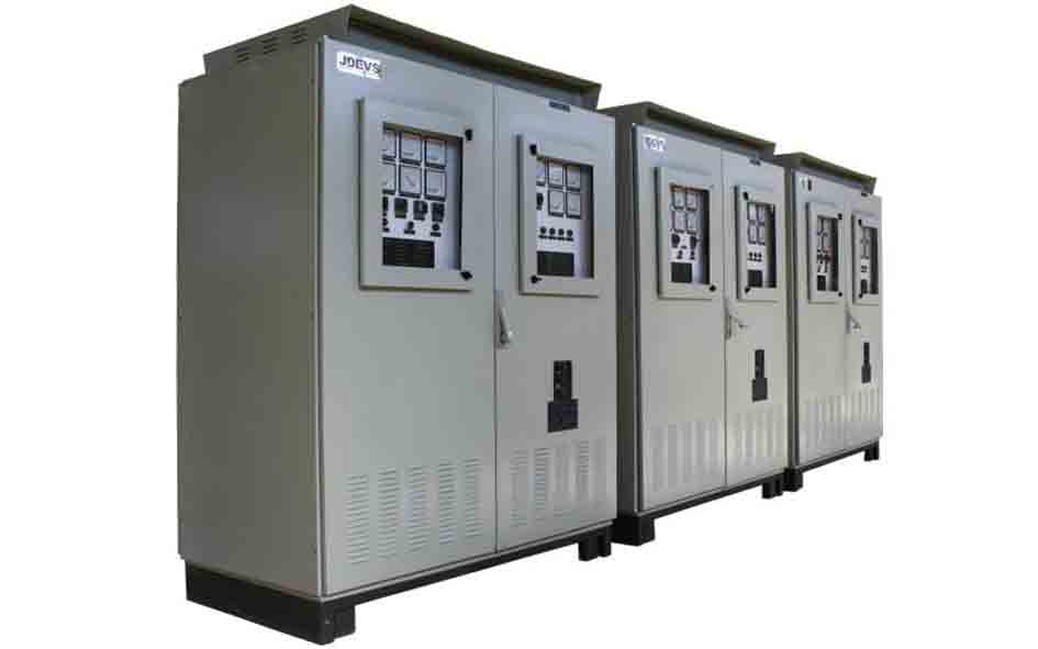
- The JDEVS UPS are base on world
- class technology with high reliability and accordance with customer's needs. used in projects of oil and gas , refineries, petrochemicals and power plants.

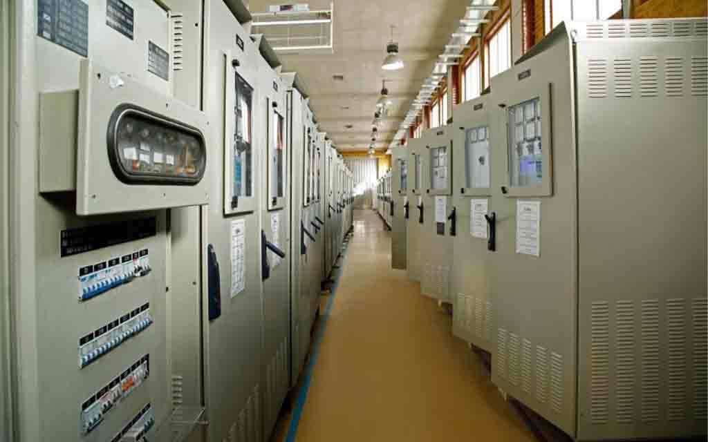
- The JDEVS industrial Battery Chargers are constant Voltage,Current Limited, 6 or 12 pulses Technology & based on power electronic converters. The battery charger designed and constructed without any limitation in current and output voltage and according to customer requirements

- Its main characteristics are: Traction motors are designed and manufactured compatible with power electronics converters, Equipped with temperature sensors installed inside the motor, Use of insulation with a temperature tolerance of up to 200 ℃, and Tested up to 4300 rpm.

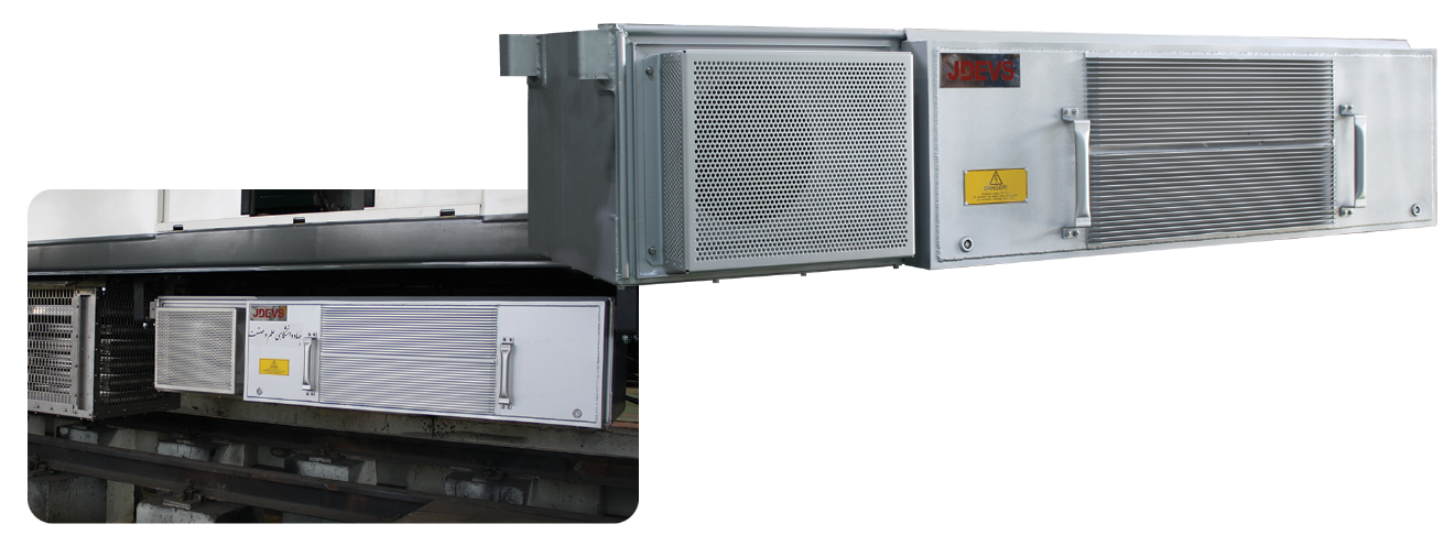
- Its main characteristics are: Ability to manufacture at various operating voltages and a wide range of acceptable voltage variations, Easy maintenance and repair thanks to the modular design of advanced equipment and systems, Optical isolation between control and power systems, Can be manufactured for different powers, Communication with control system via MVB, ETB, CAN and other communication buses, IGBT drive boards, specific for the railway applications, Compressed air cooling system and two
- speed ventilation system, and Compliant with below standards EN 50207:2001 & EN 61287_1:2014 standards.

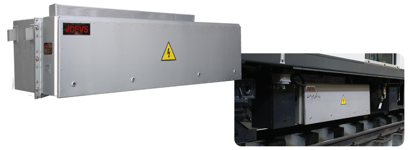
- HV
- BOX is comprised of High speed circuit breaker or protective fuses converter, Charging circuits and converter separator contactor, DC link voltage monitoring circuits, Workshop connection and ground switch.


- The following are some of the basic train operation needs which is done by VCU: Control of train propulsion and braking, Control of auxiliary converters and battery chargers, Monitoring and driver
- assistance systems, Equipped with data communication with other subsystems ( CAN, ETB, MVB, ... ), Maintenance diagnosis and assistance system.


- Its main characteristics are: Gearboxes are equipped with automatic lubrication system in both directions, i.e. CW (clockwise) and CCW (counter clockwise), Gearbox ratio can be changed according to the system design, Couplings have three degrees of freedom, the gearbox is equipped with a revolution counting gear which is used in the speed control system.