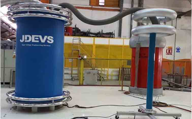
MODULAR TEST SYSTEM (AC, DC AND IMPULSE)
Usage:
- One to three stages assembly circuit
- AC circuit
- Stage 1:
- Un=100 Kv rms
- Pn=5[kVA]
- In=50[mA]
- f=50[Hz] 4 @ Uk%
- Stage two:
- Un=200[kVrms]
- Pn=5[kVA]
- In=25[mA]
- f=50[Hz] 10 @ Uk%
- stage three:
- Un=300[kVrms]
- Pn=5[kVA]
- In=16[mA]
- f=50[Hz] 14@Uk%
- DC circuit
- Stage 1:
- Un=140[kV]
- In=13[mA]
- f=50[Hz]
- Stage two
- Un=280[kV]
- In=10[mA]
- f=50[Hz]
- Stage three
- Un=400[kV]
- In=7.5[mA]
- f=50[Hz]
- Low energy impulse circuit
- Stage 1:
- Us=140[kV]
- Ws=100[J]
- Cs=10[nF]
- Voltage efficiency (Cs = 10) approx. 90%
- Stage 2:
- Us=280[kV]
- Ws=200[J]
- Cs=10[nF] Voltage efficiency (Cs = 10) approx. 90%
- Stage 3
- Us=420[kV]
- Ws=290[J]
- Cs=10[nF] Voltage efficiency (Cs = 10) approx. 90%
Related Products


